Deni Aditiya my name, my friends used to call me Dean, my goal to make this blog is to share the knowledge and experience I have and in order to solve the tasks given to the subject of knowledge management. Actually I've been wanting to share the knowledge I have done this but just now.
My competence is the field of information systems in accordance with my department now, I am very interested in everything about computers because I think computers will ever evolving seiiring changing times and I realize it was that I wanted to develop it. In addition to other competencies are in the field of robotics, I think this is very exciting field to be studied and developed, I've done some experiments and generate a simple robots. In the field of information systems I've produced several desktop and web-based program. I mastered several programming languages including C + + programming language, Visual Basic, PHP and HTML. I am still not proficient in programming languages, so I still have to develop it again.
Jumat, 30 Maret 2012
Rabu, 28 Maret 2012
My experience makes the PCB board
In
this article I will share the knowledge I am in making PCB board
(circuit board) in a manufacturing robot I do I make my own sensors on
the robot, robot sensors I have made the Proximity sensor or proximity
sensor using 2 pieces of LED, in addition to I've made an intelligent system that I gave the name Smart Lock, a tool that is used as a safety lock on the motor. until now i still develop because there are still many shortcomings.
Okay back to our topic is how to make circuit boards. Before making the first circuit board that we have to do them
1. What kind of device that we will make
2. What are the electronic components needed to make the devices.at this stage we need to understand the characteristics of electronic components that will be used to assemble the device. this is necessary because if we are wrong to use the electronic components of the device we will later make are not the result that it will not even run
3.Membuat schematic designThis is usually known as a blue print, the schematic relationship between the electronic components described in detail and this may be a reference when the device that we created later have problems.
4. convert a schematic into a PCB designHaving ascertained the schematic is correct next step is to make the PCB design, usually in software to make the PCB provided a feature to convert schematic to PCB design. One of them that I use is to use software Diptrace

5. Print the PCB design to PCB boardThere are various techniques for print design to the PCB board. Yanng one of the techniques I use is to print the PCB design to a sheet of photographic paper and then I put that there is a PCB design surface and then heating it with iron, with the heating technique, the design will be glued to the PCB board

6. Dissolving the PCB board with FeCl3 (ferry chloride)Once the design is attached to the PCB board dissolves the board next to the ferry chloride chemicals, these chemicals serve to dissolve the copper, so copper is not closed design will dissolve.
7. Installing electronic componentsafter the PCB board so then we put electronic components.
Similarly, my experience in making circuit boards
Okay back to our topic is how to make circuit boards. Before making the first circuit board that we have to do them
1. What kind of device that we will make
2. What are the electronic components needed to make the devices.at this stage we need to understand the characteristics of electronic components that will be used to assemble the device. this is necessary because if we are wrong to use the electronic components of the device we will later make are not the result that it will not even run
3.Membuat schematic designThis is usually known as a blue print, the schematic relationship between the electronic components described in detail and this may be a reference when the device that we created later have problems.
4. convert a schematic into a PCB designHaving ascertained the schematic is correct next step is to make the PCB design, usually in software to make the PCB provided a feature to convert schematic to PCB design. One of them that I use is to use software Diptrace
5. Print the PCB design to PCB boardThere are various techniques for print design to the PCB board. Yanng one of the techniques I use is to print the PCB design to a sheet of photographic paper and then I put that there is a PCB design surface and then heating it with iron, with the heating technique, the design will be glued to the PCB board
6. Dissolving the PCB board with FeCl3 (ferry chloride)Once the design is attached to the PCB board dissolves the board next to the ferry chloride chemicals, these chemicals serve to dissolve the copper, so copper is not closed design will dissolve.
7. Installing electronic componentsafter the PCB board so then we put electronic components.
Similarly, my experience in making circuit boards
Role of social networks in the development of knowledge
Social Networking or Social Networking is a concept that can be utilized in the development of education. Social networking is applied in the form of social networking sites. Besides useful to establish Silaturrahim also useful to support in improving the effectiveness of learning. Form of social networking can be developed by forming a community of learning and discussion groups according to interests and areas of the people involved.

Social networking sites or other terms of social networking sites continue to develop. We can use social networking sites like Facebook (http://www.facebook.com), My Space (http://www. Myspace.com), Friendster (http://friendster.com), Library Thing (http: / / www. librarything.com). these sites can be used not only to interact with friends, but more than that can be used as a study group discussions, assignments, or sharing the latest information.
Forms of learning that can be exploited using these social networking sites such as:
Forms of learning that can be exploited using these social networking sites such as:

That there is potential profiles on these social networks can enhance the learning process digitally. In addition to positive potentials, there is also a danger to privacy or private area for individual users to publish their profiles publicly. To anticipate able to adjust the setting and consider which ones should be displayed to the public and where the only personal.
2. Function Collaborative Authoring Platform
2.1 For User AuthorizationUser Authorization is related to the directory entry password and valid email address. This limits access by anyone outside the network and allows for a contact in the group.
2.2 For User Authorization
Collaborative work requires a way to edit and share files. With documents, upload documents and share control to do authoring.Otorisasi document is divided into three levels:
A. Member Level
Each member has its own storage.
B. cluster Level
Cluster Shared Folder Management, where members of the cluster dapatbberbagi their documents and make it visible for members clusterlainnya.
C. Network Level
System provides the ability for network members to share knowledge to maintain a shared network directory. This directory can diaksesoleh all network members.
2.3 As a Memory of the CoP for Documentation
All documents (data, information and knowledge) associated with the cycle of knowledge and can be archived. The documents include the data collected, the individual studies, group reports, proposals and research reports to help members share their knowledge and collaboration.
2.4 As a Platform for Threaded Discussion
Common space for members to discuss issues concerning joint research activities, this will promote the exchange and sharing of knowledge, understanding, models and insights from an individual prosesdiskusi.
2.5 As a Means of Communication through Quick Messaging and Emails
Users can send messages or e-mail to all group members with ease using a customized address book.
2.6 As a Tool for Time Management
A calendar function is established for the user to set time schedule.
2.7 As a Tool for Online Discussions through Chat Rooms
Members can use the chat room to discuss different issues related to online activities with them.
2.8 Coordination
Login log records the activities of the activities. Document manager, profile management, and managers are included in cluster coordination component.

Social networking sites or other terms of social networking sites continue to develop. We can use social networking sites like Facebook (http://www.facebook.com), My Space (http://www. Myspace.com), Friendster (http://friendster.com), Library Thing (http: / / www. librarything.com). these sites can be used not only to interact with friends, but more than that can be used as a study group discussions, assignments, or sharing the latest information.
Forms of learning that can be exploited using these social networking sites such as:
Forms of learning that can be exploited using these social networking sites such as:
- Made with a group that addresses one area such as information systems.
- Creating a group in general limits or only a limited area, school or just limited to certain subjects
- Creating a small group of a dozen people who only accept members upon approval.
- Sends a message to all members and asked for a response.
That there is potential profiles on these social networks can enhance the learning process digitally. In addition to positive potentials, there is also a danger to privacy or private area for individual users to publish their profiles publicly. To anticipate able to adjust the setting and consider which ones should be displayed to the public and where the only personal.
2. Function Collaborative Authoring Platform
2.1 For User AuthorizationUser Authorization is related to the directory entry password and valid email address. This limits access by anyone outside the network and allows for a contact in the group.
2.2 For User Authorization
Collaborative work requires a way to edit and share files. With documents, upload documents and share control to do authoring.Otorisasi document is divided into three levels:
A. Member Level
Each member has its own storage.
B. cluster Level
Cluster Shared Folder Management, where members of the cluster dapatbberbagi their documents and make it visible for members clusterlainnya.
C. Network Level
System provides the ability for network members to share knowledge to maintain a shared network directory. This directory can diaksesoleh all network members.
2.3 As a Memory of the CoP for Documentation
All documents (data, information and knowledge) associated with the cycle of knowledge and can be archived. The documents include the data collected, the individual studies, group reports, proposals and research reports to help members share their knowledge and collaboration.
2.4 As a Platform for Threaded Discussion
Common space for members to discuss issues concerning joint research activities, this will promote the exchange and sharing of knowledge, understanding, models and insights from an individual prosesdiskusi.
2.5 As a Means of Communication through Quick Messaging and Emails
Users can send messages or e-mail to all group members with ease using a customized address book.
2.6 As a Tool for Time Management
A calendar function is established for the user to set time schedule.
2.7 As a Tool for Online Discussions through Chat Rooms
Members can use the chat room to discuss different issues related to online activities with them.
2.8 Coordination
Login log records the activities of the activities. Document manager, profile management, and managers are included in cluster coordination component.
Sabtu, 24 Maret 2012
Fire Fighter Robot
This is the last project that I made during the semester holidays last february. This robot is not equipped with fire sensors, as sensors for detecting a fire is very expensive and not affordable to me. so I use the TV Remote to control the robot motion and put the fire out. to put the fire out of this robot uses a computer cooling fan. that this robot can walk on many fronts I use a chain wheel like a tank, and use the gearbox so it is strong enough to pass through obstacles in fighting the fire.
 Video:
Program:
Program:
int RECV_PIN = 11;
IRrecv irrecv(RECV_PIN);
decode_results results;
void setup()
{
Serial.begin(9600);
irrecv.enableIRIn(); // Start the receiver
pinMode(2,OUTPUT); // kendali motor 1
pinMode(3,OUTPUT); // motor 1 +
pinMode(4,OUTPUT); // motor 1 -
pinMode(5,OUTPUT); // kendali motor 2
pinMode(6,OUTPUT); // motor 2 +
pinMode(7,OUTPUT); // motor 2 -
}
void kanan(void){
digitalWrite(2,LOW);
digitalWrite(5,LOW);
delayMicroseconds(100);
digitalWrite(3,HIGH);
digitalWrite(4,LOW);
delayMicroseconds(100);
digitalWrite(6,LOW);
digitalWrite(7,HIGH);
delayMicroseconds(100);
digitalWrite(2,HIGH);
digitalWrite(5,HIGH);
delayMicroseconds(200);
}

void kiri(void){
digitalWrite(2,LOW);
digitalWrite(5,LOW);
delayMicroseconds(100);
digitalWrite(3,LOW);
digitalWrite(4,HIGH);
delayMicroseconds(100);
digitalWrite(6,HIGH);
digitalWrite(7,LOW);
delayMicroseconds(100);
digitalWrite(2,HIGH);
digitalWrite(5,HIGH);
delayMicroseconds(200);
}
void maju(void){
digitalWrite(2,LOW);
digitalWrite(5,LOW);
delayMicroseconds(100);
digitalWrite(3,LOW);
digitalWrite(4,HIGH);
delayMicroseconds(100);
digitalWrite(6,LOW);
digitalWrite(7,HIGH);
delayMicroseconds(100);
digitalWrite(2,HIGH);
digitalWrite(5,HIGH);
delayMicroseconds(200);
}
void mundur(void){
digitalWrite(3,HIGH);
digitalWrite(4,LOW);
delayMicroseconds(100);
digitalWrite(6,HIGH);
digitalWrite(7,LOW);
delayMicroseconds(100);
digitalWrite(2,HIGH);
digitalWrite(5,HIGH);
delayMicroseconds(200);
}

void henti(void){
// berhenti
digitalWrite(3,LOW);
digitalWrite(4,LOW);
delayMicroseconds(100);
digitalWrite(6,LOW);
digitalWrite(7,LOW);
delayMicroseconds(100);
digitalWrite(2,LOW);
digitalWrite(5,LOW);
delayMicroseconds(200);
}
void loop() {
if (irrecv.decode(&results)) {
if((results.value)== 2049||(results.value)== 1){
maju();
delay(10);
}
if((results.value)== 2052||(results.value)== 4){
kiri();
delay(10);
}
if((results.value)== 2053||(results.value)== 5){
henti();
delay(10);
}
if((results.value)== 2054||(results.value)== 6){
kanan();
delay(10);
}
if((results.value)== 2057||(results.value)== 9){
mundur();
delay(10);
}
irrecv.resume(); // Receive the next value
}

}
Jumat, 23 Maret 2012
Obstacle robot (penghindar rintangan)
As the name suggests this robot can avoid obstacles in front of him. this can be done because the robot is equipped with infrared sensors to detect obstacles. same as line follower, the robot is equipped with 2 sensors only have a slightly different program. infrared sensor in addition I also added a sensor to capture the signal from the TV remote so the robot can be controlled by TV remote, but if there are obstacles in front of the robot will escape automatically. thus the robot will not be hit if there is no obstacle in front of him.
Program:
Check this video
Program:
#include <IRremote.h>

int RECV_PIN = 11;
IRrecv irrecv(RECV_PIN);
decode_results results;
void setup()

{

  Serial.begin(9600);
  irrecv.enableIRIn(); // Start the receiver
  pinMode(2,OUTPUT);  // kendali motor 1
  pinMode(3,OUTPUT);  // motor 1 +
  pinMode(4,OUTPUT);  // motor 1 -
  pinMode(5,OUTPUT);  // kendali motor 2
  pinMode(6,OUTPUT);  // motor 2 +
  pinMode(7,OUTPUT);  // motor 2 -
}
void kiri(void){
  digitalWrite(2,LOW);
  digitalWrite(5,LOW);
  delayMicroseconds(100);
  digitalWrite(3,HIGH);
  digitalWrite(4,LOW);
  delayMicroseconds(100);
  digitalWrite(6,LOW);
  digitalWrite(7,HIGH);
  delayMicroseconds(100);
  digitalWrite(2,HIGH);
  digitalWrite(5,HIGH);
  delayMicroseconds(200);
}

void kanan(void){
  digitalWrite(2,LOW);
  digitalWrite(5,LOW);
  delayMicroseconds(100);
  digitalWrite(3,LOW);
  digitalWrite(4,HIGH);
  delayMicroseconds(100);
  digitalWrite(6,HIGH);
  digitalWrite(7,LOW);
  delayMicroseconds(100);
  digitalWrite(2,HIGH);
  digitalWrite(5,HIGH);
  delayMicroseconds(200);
}
void maju(void){
  digitalWrite(2,LOW);
  digitalWrite(5,LOW);
  delayMicroseconds(100);
  digitalWrite(3,LOW);
  digitalWrite(4,HIGH);
  delayMicroseconds(100);
  digitalWrite(6,LOW);
  digitalWrite(7,HIGH);
  delayMicroseconds(100);
  digitalWrite(2,HIGH);
  digitalWrite(5,HIGH);
  delayMicroseconds(200);
}
void mundur(void){
  digitalWrite(3,HIGH);
  digitalWrite(4,LOW);
  delayMicroseconds(100);
  digitalWrite(6,HIGH);
  digitalWrite(7,LOW);
  delayMicroseconds(100);
  digitalWrite(2,HIGH);
  digitalWrite(5,HIGH);
  delayMicroseconds(200);
}

void henti(void){
  // berhenti
  digitalWrite(3,LOW);
  digitalWrite(4,LOW);
  delayMicroseconds(100);
  digitalWrite(6,LOW);
  digitalWrite(7,LOW);
  delayMicroseconds(100);
  digitalWrite(2,LOW);
  digitalWrite(5,LOW);
  delayMicroseconds(200);
}
void loop() {
  int sensor,sensor2;
   if (irrecv.decode(&results)) {
      Serial.println(results.value);
     if((results.value)== 520||(results.value)== 2568){
maju();
        delay(10);
     }
     if((results.value)== 536||(results.value)== 2584){
        kiri();
        delay(10);
     }
    if((results.value)== 546||(results.value)== 2594){
        henti();
        delay(10);
     }
    if((results.value)== 528||(results.value)== 2576){
        kanan();
        delay(10);
     }
    if((results.value)== 516||(results.value)== 2564){
        mundur();
        delay(10);
     }
     irrecv.resume(); // Receive the next value
   }
  /* int sensor,sensor2;
  baca nilai sensor di PIN A0 (Analog) dan kirim ke serial*/
  sensor=analogRead(A0);//kanan
  sensor2=analogRead(A1); //kiri

if(sensor<=900 || sensor2<=900){
  if(sensor<sensor2){
    kiri();}
    delay(200);
  if(sensor2<sensor){
    kanan();}
   delay(200);
  }

}
Check this video
Line Follower Robot
Line follower robot is a robot that is often contested because it is quite simple for the beginner like me. This robot uses Infra red sensor to detect or recognize the line. The sensor consists of two pieces of infrared LEDs, a single transceiver and the other one as receiver. Working principle is

Line follower robot that I made consisting of two pairs of infrared sensors. the way it works is if the right sensor over the line then the robot will move left, if left out of the line sensor, the robot will move to right.
Here's video line follower robot that I made
and this program
IR LED emits infrared radiation. This radiation
illuminates the surface in front of LED. Surface reflects the infrared
light. Depending on reflectivity of the surface, amount of light
reflected varies. This reflected light is made incident on reverse
biased IR sensor. When photons are incident on reverse biased junction
of this diode, electron-hole pairs are generated, which results in
reverse leakage current. Amount of electron-hole pairs generated depends
on intensity of incident IR radiation. More intense radiation results
in more reverse leakage current. This current can be passed through a
resistor so as to get proportional voltage. Thus as intensity of
incident rays varies, voltage across resistor will vary accordingly.
This voltage can then be given to OPAMP based
comparator.Output of the comparator can be read by uC. Alternatively,
you can use on-chip ADC in AVR microcontroller to measure this voltage
and perform comparison in software.
( sumber: IR sensor)
Line follower robot that I made consisting of two pairs of infrared sensors. the way it works is if the right sensor over the line then the robot will move left, if left out of the line sensor, the robot will move to right.
Here's video line follower robot that I made
and this program
void setup() {
  pinMode(2,OUTPUT);  // kendali motor 1
  pinMode(3,OUTPUT);  // motor 1 +
  pinMode(4,OUTPUT);  // motor 1 -
  pinMode(5,OUTPUT);  // kendali motor 2
  pinMode(6,OUTPUT);  // motor 2 +
  pinMode(7,OUTPUT);  // motor 2 -
  //pinMode(13,OUTPUT); // Buzzer
  Serial.begin(9600);
}
void kanan(void){
  digitalWrite(2,LOW);
  digitalWrite(5,LOW);
  delayMicroseconds(100);
  digitalWrite(3,HIGH);
  digitalWrite(4,LOW);
  delayMicroseconds(100);
  digitalWrite(6,LOW);
  digitalWrite(7,HIGH);
  delayMicroseconds(100);
  digitalWrite(2,HIGH);
  digitalWrite(5,HIGH);
  delayMicroseconds(200);
}

void kiri(void){
  digitalWrite(2,LOW);
  digitalWrite(5,LOW);
  delayMicroseconds(100);
  digitalWrite(3,LOW);
  digitalWrite(4,HIGH);
  delayMicroseconds(100);
  digitalWrite(6,HIGH);
  digitalWrite(7,LOW);
  delayMicroseconds(100);
  digitalWrite(2,HIGH);
  digitalWrite(5,HIGH);
  delayMicroseconds(200);
}
void maju(void){
  digitalWrite(2,LOW);
  digitalWrite(5,LOW);
  delayMicroseconds(100);
  digitalWrite(3,LOW);
  digitalWrite(4,HIGH);
  delayMicroseconds(100);
  digitalWrite(6,LOW);
  digitalWrite(7,HIGH);
  delayMicroseconds(100);
  digitalWrite(2,HIGH);
  digitalWrite(5,HIGH);
  delayMicroseconds(200);
}
void henti(void){
  digitalWrite(2,LOW);
  digitalWrite(5,LOW);
  delayMicroseconds(100);
  digitalWrite(3,LOW);
  digitalWrite(4,LOW);
  delayMicroseconds(100);
  digitalWrite(6,LOW);
  digitalWrite(7,LOW);
  delayMicroseconds(100);
  digitalWrite(2,LOW);
  digitalWrite(5,LOW);
  delayMicroseconds(200);
}


void loop() {
  int sensor,sensor2;
  // baca nilai sensor di PIN A0 (Analog) dan kirim ke serial
  sensor=analogRead(A0);//kanan
  sensor2=analogRead(A1); //kiri
  Serial.println(sensor);

if(sensor>=900&&sensor2>=900) {
  maju();
//digitalWrite(13,LOW);
}
if (sensor<900){
kiri();
}
if(sensor2<900){
  kanan();
}
if(sensor<900 && sensor2<900){
  henti();
  delay(200);
  kanan();
  if(sensor >= 900 || sensor2 >= 900) {
    maju();
  }
  delay(500);
}
}
My first robot (IR remot)
This is my first project in the field of robotics, the robot is equipped with an infrared sensor signal receiver, I get the sensor from the former television obsolete. With this sensor robot can receive remote commands from the television which are then processed by a microcontroller that has been my program then responds in the form of motion commands. This robot is programmed using the programming language C. Not so hard I was using the C programming language, because in the first semester I got the course Algorithms and data structures to learn the programming language C.
My first robot

and this video
My first robot
and this video
Kamis, 22 Maret 2012
Arduino
Arduino is an open-source electronics prototyping platform based on
flexible, easy-to-use hardware and software. It’s intended for artists,
designers, hobbyists, and anyone interested in creating interactive
objects or environments.

Arduino can sense the environment by receiving input from a variety of sensors and can affect its surroundings by controlling lights, motors, and other actuators. The microcontroller on the board is programmed using the Arduino programming language (based on Wiring) and the Arduino development environment (based on Processing). Arduino projects can be stand-alone or they can communicate with software on running on a computer (e.g. Flash, Processing,MaxMSP).
The boards can be built by hand or purchased preassembled; the software can be downloaded for free. The hardware reference designs (CAD files) are available under an open-source license, you are free to adapt them to your needs.
Arduino received an Honorary Mention in the Digital Communities section of the 2006 Ars Electronica Prix. The Arduino team is: Massimo Banzi, David Cuartielles, Tom Igoe,Gianluca Martino, and David Mellis. Credits
source: Arduino
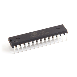
Microcontroler
A microcontroller is an integrated chip that is often part of an embedded system. The microcontroller includes a CPU, RAM, ROM, I/O ports, and timers like a standard computer, but because they are designed to execute only a single specific task to control a single system, they are much smaller and simplified so that they can include all the functions required on a single chip.
A microcontroller differs from a microprocessor, which is a general-purpose chip that is used to create a multi-function computer or device and requires multiple chips to handle various tasks. A microcontroller is meant to be more self-contained and independent, and functions as a tiny, dedicated computer.
The great advantage of microcontrollers, as opposed to using larger microprocessors, is that the parts-count and design costs of the item being controlled can be kept to a minimum. They are typically designed using CMOS (complementary metal oxide semiconductor) technology, an efficient fabrication technique that uses less power and is more immune to power spikes than other techniques.

There are also multiple architectures used, but the predominant architecture is CISC (Complex Instruction Set Computer), which allows the microcontroller to contain multiple control instructions that can be executed with a single macro instruction. Some use a RISC (Reduced Instruction Set Computer) architecture, which implements fewer instructions, but delivers greater simplicity and lower power consumption.
A microcontroller differs from a microprocessor, which is a general-purpose chip that is used to create a multi-function computer or device and requires multiple chips to handle various tasks. A microcontroller is meant to be more self-contained and independent, and functions as a tiny, dedicated computer.
The great advantage of microcontrollers, as opposed to using larger microprocessors, is that the parts-count and design costs of the item being controlled can be kept to a minimum. They are typically designed using CMOS (complementary metal oxide semiconductor) technology, an efficient fabrication technique that uses less power and is more immune to power spikes than other techniques.
There are also multiple architectures used, but the predominant architecture is CISC (Complex Instruction Set Computer), which allows the microcontroller to contain multiple control instructions that can be executed with a single macro instruction. Some use a RISC (Reduced Instruction Set Computer) architecture, which implements fewer instructions, but delivers greater simplicity and lower power consumption.
Langganan:
Postingan (Atom)